
Comparing induction motors, permanent-magnet motors, and servomotors

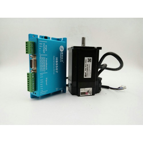
Hybrid Stepper Motor
The hybrid stepper motor uses the principles of the permanent magnet and variable reluctance stepper motors. In the hybrid stepper motor, the rotor flux is produced by the permanet magnet and is directed by the rotor teeth to the appropriate parts of the airgap.
The main flux path is from the north pole of the magnet, into the end stack, across the airgrap through the stator pole, axially along the stator, through the stator pole, across the air gap and back to the magnet south pole via the other end stack.
There are usually 8 poles on the stator. Each pole has between 2 to 6 teeth. There is two phase winding. The coils on poles 1,3,5 and 7 are connected in series to form phase A while the coils on poles 2,4,6 and 8 are connected in series to form phase B. The windings A and B are energised alternately.
When phase A carries positive current, stator poles 1 and 5 become south and 3 and 7 become north. The rotor teeth with north and south polarity align with the teeth of stator poles 1 and 5 and 3 and 7 respectively. When phase A is de energised and phase Bis exicited, are energised alternately.
The torque in Nema 17 stepper motor is produced by the interaction of the rotor and the stator produced fluxes. The rotor field remains constant as it is produced by the permanent magnet. The motor torque T is proporatinal to the phase current.
Following are the main advantages of the hybrid stepper motor:
1. Very small step angles upto 1.8
2. Higher torque per unit volume which is more than in cae of variable reluctance motor
3. Due to permanet magnet, the motor has some detent torque which is absent in variable reluctance motor.
These are the various types of the stepper motors. After duscussing the various types and the operating principle, let us discuss the important parameters related to a stepper motor. The stepper motor characteristics are mainly the indication of its important parameters.
1. Holding Torque:
It is defined as the maximum static torque that can be qpplied to the shaft of an excited motor without causing a continuous rotaing.
2. Detent Torque:
It is defined as the maximum static torque that can be qpplied to the shaft of an unexcited motor without causing a continuous rotation.
Under this torque the rotor comes back to the normal rest position even if excitation ceases. Such positions of the rotor are referred as the detent positions.
3. Step Angle:
It is defined as the angular displacement of the rotor in response to each input pulse.
4. Critical Torque:
It is defined as the maximum load torque at which rotor does not move when an exciting winding is energised. This is also called pullout torque.
5. Limiting Torque:
It is defined for a given pulsing rate or stepping rate measured in pulses per second, as the maximum load torque at which motor follows the control pulses without missing any step. This is also called pull in torque.
6. Synchronous stepping rate:
It is defined as the maximum rate at which the motor can step wihout missing steps. The motor can start, stop or reverse at this rate.
7. Slewing rate:
It is deined as the maximum rate at which the motor can step unidirectionally. The slewing rate is much higher than the synchronous stepping rate. Motor will not be able to stop or reverse without missing steps at this rate.

Variable Frequency Drives
A variable frequency drive (VFD) is an electronic controller that adjusts the speed of an electric motor by modulating the power being delivered. These drives provide continuous control, matching motor speed to the specific energy demands. In other words, the YASKAWA VFD controls the rotational speed of an AC electric motor by controlling the frequency of the electrical power supplied to the motor. A variable frequency drive has the potential to be a significant cost-saving device for water and wastewater facilities. Variable frequecy drives are an excellent choice for adjustable speed drive users because they allow operators to fine-tune processes while reducing costs for energy and equipment maintenace.

Variable frequency drives are used in a wide number of applications to control pumps, fans, hoists, conveyors, and other machinery. They are enjoying increasing popularity at water and wastewater facilities, where the greatest energy draw comes from pumping and aeration-two applications particularly suited to variable frequency drives.
For applications where flow requirements vary, mechanical devices such as flow-restricting valves or moveable air vanes are often used to control flow, which is akin to driving a car at full throttle while using the brake to control speed. This process uses excessive energy an may create punishing conditions for the mechanical equipment involved. Variable frequency drives enable pumps to accommodatd fluctuating demand by running pumps at lower speeds and drawing less energy while still meeting pumping needs.
As shown in Figure 5.3, a variable frequency drive systems generally consists of an AC motor, a controller, and an operator interface. Variable frequency drives work with most threee phase electric motors, so existing pumps and blowers that use throttling devices can be retrofit with these controls. Delta VFD can also be specified for new equipment.
A huge advantage of variable frequency drives is that they give a single-speed drive motor a "soft-start" capability, gradually increasing the motor to high torque and current surges up to 10 times the full-load current. If normal operating load current is 10 apms, for example, that motor could draw 100 amps at start. The VFD soft-start capability lessens mechanical and electrical stress on the motor system, can reduce maintenance and repair costs, and can extend motor life.
In addition to their soft-start capability, variable frequency drives allow more precise control of process such as water distribution, aeration, and chemical feed. Pressure in water distribution systems can be maintained to closer tolerances. Wastewater treatment plants can consistently maintain desired dissolved oxygen concentrations over a wide range of flow and biological loading conditions by using automated controls to link disolved oxgen sensors to variable frequency drives on the aeration blowers.

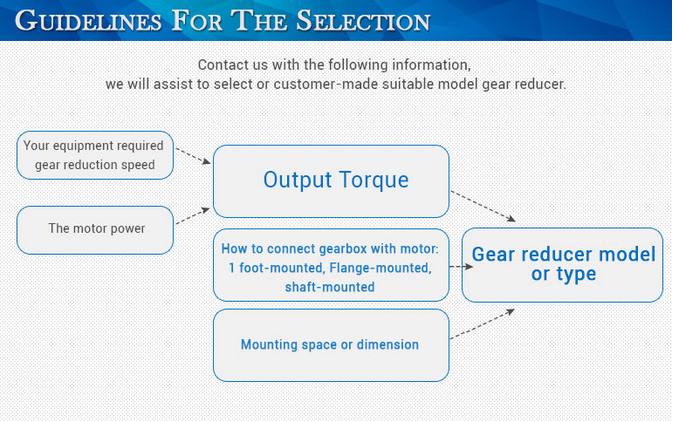
The Type of Gear Reducers

Stepper Drive Modes
This chapter has explained how to operate steppers by energizing one or two winding pairs at a tiem, but tere are a number of different ways to drive a Nema 23 stepper motor, and this discussion touches on four of them:
* Full-step (one phase on) mode - Each control signal energizes on winding.
* Full-step (two phases on) mode - Each control signal energizes two windings.
* Half-step mode - Each control signal alternates between energizing one and two windings.
* Microstep mode - The controller delivers sinusoidal signals to the stepper's windings.
Full-Step (One Phase On) Mode
The simplest way to control a stepper is to energize one winding at a time. This is the method discussed at the start of this chapter. Figure 4.15 shows what the signaling sequence looks lide when controlling a stepper motor drive in this mode.

With each control signal, the rotor truns to align itself with the energized winding. The rotor always turns through the stepper's rated step angle. That is, if a PM motor is rated for 7.5, each control signal causes it to turn 7.5.
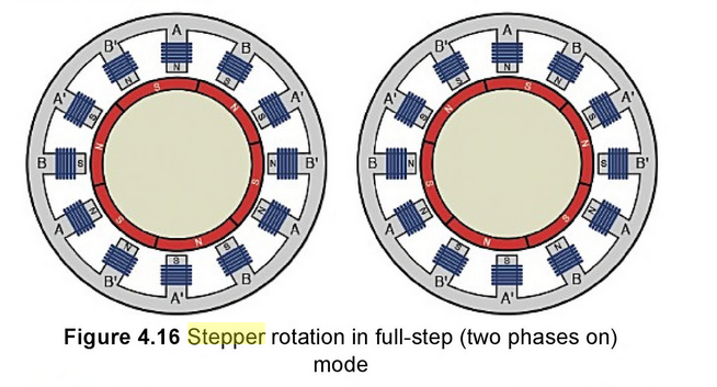
Full-Step (Two Phase On) Mode
In the full-step (two phase on) mode, the controller energizes two windings at once. This turns the rotor through the stepper's rated angle, and the rotor always aligns itself between two windings. Figure 4.16 illustrates one rotation of a stepper motor driven in this mode.
Figure 4.17 shows what the corresponding drive sequence looks like.
The main advantage of this mode over full-step (one phase on) is that it improves the motor's torque. Because two windings are always on, torque increases by approximately 30%-40%. The disadvantage is that the power supply has to provide twice as much current to turn the stepper.
Half-Step Mode
The half-step mode is like a combination of the two full-step modes. That is, the controller alternates between energizing one winding and two windings. Figure 4.18 depicts three rotations of a stepper in half-step mode.
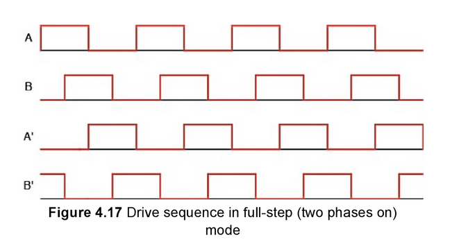
Figure 4.19 illustrates a control signal for a stepper motor driven in half-step mode.
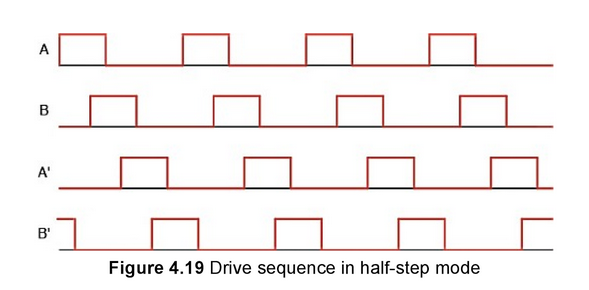
In this mode, the rotor aligns itself with windings (when one winding is energized) and between windings (when two windings are energized). This effectively reduces the motor's step angle by half. That is, if the stepper's step angle is 1.8, it will trun at 0.9 in half-step mode.
The disadvantage of this mode is that, when a single winding is energized, the rotor turns with approximately 20% less toruqe. This can be compenstated for by increasing the current.
Microstep Mode
The purpose of microstep mode is to have the stepper turn as smoothly as possible. This requires dividing the energizing pulse into potentially hundreds of control signals. Common numbers of division are 8,64,and 256. If the energizing pulse is divided into 256 signals, a 1.8 stepper will turn at 1.8/256=0.007 per control signal.
In this mode, the controller delivers current in a sinusoidal pattern. Successive windings receive a delayed version of this sinusoid. Figure 4.20 gives an idea of what this looks like.
Using this mode reduces torque by nearly 30%, but another disadvantage involes speed. As the width of a control signal decrease, the ability of the motor to respond also decrease. Therefore, if the controller delivers rapid pulses to the stepper in microstep mode, the motor may not turn in a reliable fashion.

Sychronous type AC Servo Motor
The stator consists of a cylindrical frame and a stator core. The stator core is located in the frame and an armature coil is wound around the stator core. The end of the coil is connected with a lead wire and current is provide from the lead wire. The rotor consists of a shaft and a permanent magnet and the permanent magnet is attached to the outside of the shaft. In a synchronous type AC Leadshine servo motor, the magnet is attached to a rotor and an armature coil is wound around the stator unlike the DC servo motor. Therefore, the supply of current is possible from the outside without a stator and a synchronous type AC servo motor is called a "brushless servo motor" because of this structural characteristic. Because this structure makes it possible to cool down a stator core directly from the outside, it is possible to resist an increase in temeprature. Also, because a synchronous type AC servo motor does not have the limitation of maximum velocity due to recification spark, a good characteristic of torque in the high-speed range can be obtained. In additon, because this type of motor has no brush, it can be operated for a long time without maintenace.
Like a DC servo motor, this type of AC servo motor uses an optical encoder or a resolver as a detector of rotation velocity. Also, a ferrite magnet or a rate earth magnet is used for the magnet which is built into the rotor and plays the role of a field system.
In this type of AC mitsubishi servo motors, because an armature contribution is linearly proportional to torque. Stop is easy and dynamic brake wordks during emergency stop. However, because a permanent magnet is use, the structure is very complex and the detection of position of the rotor is needed. The current from the armature includes high frequency current and the high frequecy current is the source of toruqe ripple and vibration.

The Need for Variable Frequency Drives
There are many and diverse reasons for using Variable Frequency Drives. Some applictaions, such as paper making machines, cannot run without them while others, such as centrifugal pumps, can benefit from energy savings.
In general, Delta VFD are used to:
Match the speed of a drive to the process requirements
Match the torque of a drive to the process requirements
Save energy and improve efficency
The needs for speed and torque control are usually fairly obvious. Modern electrical YASKAWA VFD can be used to accurately maintain the speed of a driven machine to within ±0.1%, independent of load, compared to the speed regulation possible with a conventional fixed speed squirrel cage induction motor, where the speed can vary by as much as 3% from no load to full load.
Many people in the industry think control methods are the sequencing methods that control VFDs, as in 2- and 3-wire setups. Such 2- and 3-wire setups determine whether a VFD’s input-control terminals interface with maintained contacts or momentary push buttons to start and stop the drive. The control methods this article focuses on are perhaps more accurately called motor-control methods. They determine how VFDs control motors.
The benefits of energy savings are not always fully appreciated by many users. These savings are particulary apparent with centrifugal pumps and fans, where load torque increas as the square of the speed and power consumption as the cube of the speed. Substantial cost savings can be achieved in some applications.
An everyday example, which illustrates the benefits of variable speed control, is the motorcar. It has become such as an integral part of our lives that we seldom think about the technology that it represents or that it is simply a variable speed platfrom. It is used here to illustrate how Variable Frequency Drives are used to improve the speed, torque and energy performance of a machine.
It is intuitively obvious that the speed of a motorcar must continuously be controlled by the driver (the operator) to match the traffic conditions on the road (the process). In a city, it is necessary to obey speed limits, avoid collisions and to start, accelerate, decelerate and stop when required. On the open road, the main objective is to get to a destination safely in the shortest time without exceeding the speed limit. The two main controls that are used to control the speed are the accelerator, which controls the driving torque, and the brake, which adjusts the load torque. A motorcar could not be safely operated in city traffic or on the open road without these two controls. The driver must continuously adjust the fuel input to the engine (the drive) to maintain a consistant speed in spite of the changes in the load, such as an uphill, downhill or strong wind conditions. On other occasions he may have to use the brake to adjust the load and slow the vehicle down to standstill.
Another important issue for most drivers is the cost of fuel or the cost of energy consumption. The speed is controlled via the accelerator that controls the fuel input to the engine. By adjusting the accelerator position, the energy consumption is kept to a minimum and is mached to the speed and load conditions. Imageine the high fuel comsumption of a vehicle using a fixed accelerator setting and controlling the speed by means of the brake position.

How Does an AC motor work
AC motors are powered with alternating present and convert electrical power into mechanical power. You will find 3 kinds of alternating present motors with three-phases. Nema 17 stepper motor probably the most generally utilized, for AC voltage, the voltage on which they run, is readily accessible at any outlet. All AC motors, regardless of their kind, are comprised of a stator, which produces the magnetic field, along with a rotor, that is produced to rotate by the magnetic field that's induced in the present generated by the stator.
When selecting the proper hybrid stepper motor for the application you will find two important elements to bear in mind; the operating speed, or how quick the motor will turn as measured in RPMS, and also the beginning torque, or just how much force is required (if any) to begin the motor. By supplying these specifications to an skilled engineer, you are able to make sure you'll obtain probably the most efficient and price effective AC motor for the application.
In contrast to toys and flashlights, most houses, offices, factories, as well as other buildings are not powered by small batteries: they are not supplied with DC present, but with alternating present (AC), which reverses its path about 50 occasions per second (having a frequency of 50 Hz). If you would like to run a motor out of your household AC electrical energy provide, rather than from a DC battery, you'll need a various style of motor.
In an AC motor, there is a ring of electromagnets arranged about the outdoors (creating up the stator), that are developed to create a rotating magnetic field. Inside the stator, there is a strong metal axle, a loop of wire, a coil, a squirrel cage produced of metal bars and interconnections (just like the rotating cages individuals occasionally get to amuse pet mice), or some other freely rotating metal component that may conduct electrical energy. In contrast to inside a DC motor, exactly where you send energy towards the inner rotor, in an AC motor you send energy towards the outer coils that make up the stator. The coils are energized in pairs, in sequence, creating a magnetic field that rotates about the outdoors from the motor.
How does this rotating field make the motor move? Keep in mind that the rotor, suspended inside the magnetic field, is definitely an electrical conductor. The magnetic field is continuously altering (simply because it is rotating) so, based on the laws of electromagnetism (Faraday's law, to become precise), the magnetic field produces (or induces, to make use of Faraday's personal term) an electric present inside the rotor. When the conductor is really a ring or perhaps a wire, the present flows about it inside a loop. When the conductor is merely a strong piece of metal, eddy currents swirl about it rather. Either way, the induced present produces its personal magnetic field and, based on an additional law of electromagnetism (Lenz's law) tries to quit what ever it's that causes it's the rotating magnetic field by rotating also. (You are able to believe from the rotor frantically attempting to "catch up" using the rotating magnetic field in an work to get rid of the distinction in motion in between them.) Electromagnetic induction will be the important to why a motor like this spins and that is why it is known as an induction motor.

Programming With a Rotary Axis
The final topic in this chapter is the use fo a rotary axis. A rotary 4th axis is most often found in the form of a rotary table or an indexing head. The rotary table is a device that can be fastened to the milling table and then rotated to the desired angular position with a G-code. The positioning designation for a single-axis rotary table is the letter A. Some more sophistiated rotary tables can rotate in two axes, which would be designated A and B.
Machines that support a rotary axis typically allow the table to e positioned with both the G00 code for rapid traverse and G01 for linear interpolation, and in canned cycles. When we simply want to rapid traverse the rotary table to an angular position, we are rotate the rotary table and move a linear axis, we would then call this simultaneous fourth-axis interpolation. We make this distinction because many of the CAD/CAM systems are designated as either indexing or simultaneous.

The syntax for programming a rotary table is the same as for rapid traverse and linear interpolation, and a canned cycle- we only need to add the A-word to the block. The rotary axis is simply an addition to the standard code that we are already familiar with.

The rotary aix is easy to use, but there are a few technical points that we must understand when programming. First, the A-axis will ususally have a resolution of 0.001 decimal degrees. We must always remember that as we move farther away from
the center of the axix, the linear error greatly increases. Second, the A-axis can be programmed to move in the positive or negative direction and can use absolute or incremental coordinates.

Inserting Parametric PLC Modules
A programmable logic controller (PLC) or programmable controller is a digital computer that is used to automatically regulate the industrial process. For example, comtrolling machinery on assembly lines of factor. This controller is designed to meet a range of industrial activities such as multiple inputs and output arrangements, extended temperature ranges, giving immunity to electrical noise, and providing resistance to vibration. The programs, designed to regulate the machine operation, are usually stored in a battery-backed or non-volatile memory. A PLC is an instance of a real time system becuase output results are needed to be produced in response to input conditions within a time-bound period; else, it will result in an unintended operation. Over the years, the functionality of PLC has evolvoed to accommodate sequential relay control, motion control, process control, distributed control systems, and networking. In PLC, microprocessor controlled interface is inbuilt and is designed to control or monitor some other I/O functions. Being an industrial computer control system, it always monitors the state of input devices and makes decisions on the basis of custom program for controlling the state of devices connected as outputs.
Inserting Parametric PLC Modules
AutoCAD Electrical can generate PLC I/O modules in different graphical styles through parametric generation technique on demand. These modules are generate by a database file and a library of symbol blocks. PLC I/O modules can be inserted as independent symbols. MITSUBISHI PLC behave like other schematic components. These modules are AutoCAD blocks containing attributes for connection points, tagging and so on.
The Insert PLC (Parametric) tool is used to insert a PLC module parametrically. To do so, choose the Insert PLC (PLarametric) button from the Insert Components panel of the Schematic tab; the PLC Parametric Selection dialog box will be displayed, as shown in Figure 10-1. Using this dialog box, you can select the PLC module and its graphics that you want to insert in a drawing. The different options and areas in this dialog box are discussed next.
Manufacture Catalog Tree
The Manufacture Catalog tree, shown in Figure 10-2, displays a list of PLC modules. This list can be filtered by selecting the manufacturer, series, and type of PLC. The data displayed in the Manufacturer Catalog tree is stored in the ace_plc.mdb database file.
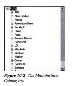
You can selet a PLC module from the Manufacturer Catalog tree. To do so, click on the + sign on the requried manfacturers module; PLC modules of the selected manafacturer will be displayed. Select the requried module from the module list; the detailed information of the selected module will be displayed at the lower part of the PLC Parametric Selection dialog box, as shown in Figure 10-3.
After specifying the required values in the I/O Point dialog box, choose the OK button from this dialog box; the I/O Address dialog box will be displayed, as shown in Figure 10-6. Using this dialog box, you can specify the address for the first I/O point. Fasttobuy offers different brands of PLC modules such as Siemens PLC, Omron PLC, Mitsubishi PLC, Delta PLC, SIEMENS PLC, OMRON PLC, Fatek PLC, ect.
The values in the Quick picks drop-down list are based on the values that you have specified in the I/O Point dialog box in the Rack and SLOT edit boxes. Select the required value from the Quick picks drop-down list; the value will be displayed in the Beginning address edit box. Alternatively, enter a required value for the first I/0 address of a PLC Module in the Beginning address edit box. Note that the other I/O points of a module will be incremented based on the value specified in the Beginning address edit box.

Choose the List button in the I/O Address dialog box; the Report Generator dialog box will be displayed. This dialog box display the information of the selected PLC module.
After specifying the required options in the I/O Address dialog box, choose the OK button in this dialog box; the selected PLC module will be inserted into the drawing.

DSP-BASED Control of Stepper Motors
A stepper motor is an electric machine that rotates in discrete angular increments or steps. Stepper motors are operated by applying current pulses of a specific frequency to the inputs of the motor. Each pulse applied to the Nema 23 stepper motor causes its shaft to the motor causes its shaft to move a certain angle of rotation, called a stepping angle. Since the input signal is converted directly into a requested shaft position without any rotor position sensors or feedback, the stepper motor has the following advantages:
- Rotational speed proportional to the frequency of input pulses
- Digital control of speed and position
- No need of feedback sensor for open loop control Excellent acceleration and deceleration responses to step commands

The stepper motor has salient poles on both the stator and the rotor, andnormally only the stator poles hold the poly-phase windings called the controlwindings. Usually stepper motors are classified as:
- Active rotor (permanent magnet rotor)
- Reactive rotor (reluctance type)
- Hybrid motors (combining the operating principles of the permanentmagnet (PM) and reluctance stepper motor)
While each of these types of stepper motors has merit, hybrid CNC stepper motor are becoming more popular in industrial applications. In this chapter, we focus onthe principles and implementation of a hybrid stepper motor control system usingthe LF2407 DSP controller.
The operation of the stepper motor relies on the simple principle of magneticattraction. This principle states that opposite magnetic poles attract while like polesrepel each other. If the windings are excited in the correct sequence, the rotor will rotate following a certain direction. The basic operation of a stepper motor can beclassified generally as either full step mode or half step mode. These modes are discussed in detail in the following section using the simplified stepper motorconstruction shown in Fig. 8.1.
Full-step Mode
If none of the stator windings are excited, an attraction between the stator polesand rotor teeth still exists because the PM rotor is trying to minimize the reluctanceof the magnetic flux path from one end to the other. As a result, the rotor will tend to rest at one of the rest equilibrium positions. From Fig. 8.1, a rest position existswhen a pair of rotor teeth are aligned with two of the stator poles. In the case ofFig. 8.1, the rotor is aligned with pole 1 and pole 3 on the stator. There are a total of12 possible equilibrium positions for a 4-phase, 6-pole stepper motor. The force ortorque that holds the rotor in one of these positions is called the detent torque. The value of the detent torque is usually small because no current flows through thestator windings.
Half-Step Mode
The stepper motor operation discussed rotates 300 per step. In the half step mode, alternately exciting one winding, then exciting two windings, will cause therotor to move through only 15 degree per step. Though there is a slight loss of thetorque while the single winding is being excited, half-step operation allows forsmoother operation at lower speeds and less overshoot at the end of each step. The excitation sequence of the stator windings in half-step mode is given in Table 8.3.During this operation, each switch between the two nearest modes will cause a 450 shift of stator field which results in a 150 rotation of the rotor. A total of 24steps are required for a complete revolution, double of what is required for full stepmodes.
Micro Step Mode
For the operating modes discussed previously, the same amount of current flows through the energized stator windings. However, if the currents are not equal, the rotor will be shifted towards the stator pole with the higher current. The amount of deviation is proportionate to the values of the currents in each winding. This principle is utilized in the microstep mode. During this mode, each basic full mode step can be divided into as many as 500 microsteps, providing the proper current profile is applied.

Spindle Motors
The motor that spins the platters is called the spindle motor because it is connected to the spindle around which the platters revolve. Spindle motors in hard disk drives are always connected directly; no belts or gears are involoved. The Air cooled spindle must be free of noise and vibration; otherwise, it can transmit a rumble to the platters, which can disrupt reading and writing operations.
The spindle motor also must be precisely controlled for speed. The platters in hard disk drives revolve at speeds ranging from 3600rpm to 15000rpm (60-250 revolutions per second) or more, and the 300W Spindle motor has a control circuit with a feedback loop to monitor and control this speed precisely. Because the speed control must be automatic, hard drives do not have a motor-speed adjustment. Some diagostics programs claim to measure hard drive rotation speed, but all these programs do is estimate the rotational speed by the timing at which sectors pass under the heads.
There is actually no way for a program to meause the hard disk drive's rotational speed; this measurement can be made only with sophisticated test equipment. Don't be alarmed if some diagnostics program tells that your drive is spinning at an incorrect speed; most likely, the program is wrong, not the drive. Platter rotation and timeing information is not provided through the hard disk controller interface. In the past, software could give approximated rotational speed estimates by performing multiple sector read requests and timing them, but this was vaild only when all drives had the same number of sectors per track and spun at the same speed. Zoned-bit recording combined with the many various rotational speeds used by modern drives, not to mention built-in buffers and caches-means that these calcualtion estimates can't be performed accurately by software.
On most drives, the spindle motor is on the bottom of the drive, just below the sealed HDA. Many drives today, however have the spindle motor built directly into the platter hub inside the HDA. By using an intermal hub spindle motor, the manufacture can stack more platter in the drive because the spindle motor takes up no vertical space.
Traditionally, spindle motors have used ball bearings in their design, but limitations in their performance have now caused drive manufactures to look for alternatives. The main problem with ball bearings is that they have approximately 0.1 micro inch (millionths of an inch) of runout, which is lateral of modern drives, it has become a problem. This runout allows the platters to move randomly that displus the metal-to-metal contact nature of ball bearings allows an excessive amount of mechanical noise and vibration to be generated, and that is becoming a problem for drives that spin at higher speeds.
The solution is a new type of bearing called a fluld dynamic bearing, which uses a highly viscous lubrication flud between the spindle and sleeve in the motor. Thi flud serves to dampen vibrations and movement, allowing runout to be reduced to 0.01 micro inches or less. Fluid dynamic bearings also allow for better shock resistance, improved speed control, and reduced noise generation. Several of the more advanced drives on the market today already incorporated fluid dynamic bearings, especially those designed for very high spindle speeds, high areal densities, or low noise. Over the next few years, I expect to see fluid dynamic bearings become standard issue in most hard drives.

Mechanical Overview of Servo Motors
Servo motors have serval distinct characteristics that sperate them from their stepper counterparts. The biggest is the lack of direct gearing between the rotor and the output shaft. This eliminates the backlash and cogging behaviors found ins steppers, where there is period of slop between the gear teeth before movement actually begins, and where the shaft continues to move after the Yaskawa servo motor has stopped. This can lead to jerky starts and stops, as well as a time delay in movement. This does not impede static positioning performance markedly, but it presents major issues when on-the-fly velocity changes or hard starts/stops are needed.
A model of a typical radial brushless DC servo motor is shown before in figure 1.1 For a long time, Mitsubishi servo drives used brushes to transfer current from the static winding to the rotor, but this would lead to wear on the brushes, in turn shortening the lifespan of the motor. With the advent of electronic motor controllers, the brusheless design was adopted, which uses control electronics to vary the currents phases to the motor's windings in the same way the brushes do. For the rest of this paper, all mention of servo motors will be of the brusheless type.
Looking at figure 1.1 below, there are several objects of interest. First are the armature windings (held by the stator), which create a magnetic field that travels through the air gap to the permanent magnets on the rotor. Even though there are normally no gears in a servo motor, cogging can still exist, as there are gaps between the magnets on the rotor where the flux decrease, though this only becomes noticeable at low speeds. This type of congging in servos is perhaps more accurately termed "detent torque." There are two ways to minimize this type of cogging, the most common being the addition of some gearing to the drive shaft. This allow the motor to run at a higher speed out of its cogging region, but does not compromise power output or precision, thought it can induce some backlash. The other way of minimizing cogging is to skew the magnets on the rotor so that a radial line from the center of the rotor always intersects a magnet at least once. When using a motor without gearing, it is known as a direct drive motor. This allows for the best transfer of power to the load, and avoids any of the negative aspects of gearing previously mentioned. A feature in newer servo motors (including the Bodine models used in this thesis) is the use of an ironless stator, which eliminates iron saturation, a situation where the magnetic properities of the iron limit how much current can be applied to the windings. Inducing iron saturation too ofen will cause overheating and possibly damage the winding or magnets. With an ironless stator, rotor magnet skewing is not necessary, as the magnetic fields aren't influenced by the material of the stator. Also, since the only mechanical connection between the shaft and the body is through the bearings, friction is very low (especialy when using ball bearings).

In high torque motors such as the ones used in this thesis, the rotor actually consists of two plates of permanet magnets sandwiching the stator, which allows for a major increase in torque. This feature only exists in axial flux motors, due to the design where the stator lies in between the rotors, whereas in radial flux servos, the rotor is completely enclosed by the stator. The majority of the heat dissipated from a servo motor comes from the stator, so its outside location adis in cooling. In fact, the main limiting fator in the power of a servo motor is the heat capacity of the stator and the armature windings.
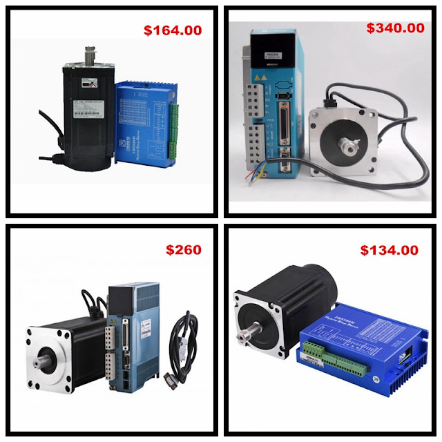
Fasttobuy Servo Motor On Sale In this September
If you are interested in these servo motor, you can click this link:

Introduction of Induction Servo Motors
The servosystem is one in which the output is some mechanical variable like position, velocity or acceleration. Such systems are generally automatic controls system which work on the error signals. The error singals are amplified to drive the motors used in such systems. Panasonic servo motor used in servosystems are called as servomotors. These motors are usually coupled to the output shaft i.e. load through gear train for power matching.
These motors are used to convert electrical signal applied, into the angular velocity or movement of shaft.
Requirements of Good Servomotor:
The servomotors which are designed for use in feed back control systems must have following requirements:
i) Linear relationship between electrical control signal and the rotor speed over a wide range.
ii) Inertia of rotor should be as low as possible. A mitsubishi servo motor must stop running without any time delay, if control signal to it is removed. For low inertia, it is designed with large length to diameter ratio, for rotors. Compared to its frame size, the rotor of a servomotor has very small diameter.
iii) It response should be as fast as possible. For quickly changing error signals, it must react with good response. This is achieved by keeping torque to weight ratio high.
iv) It should be easily reversible.
v) It should have linear torque-speed characteristics.
vi) Its operation should be stable without any oscillations or overshoots.
Types of Servomotors:
The servomotors are basically classified depending upon the nature of the electric supply to be used for its opearation.
The types of servomotors are as shown in the following chart:

A.C. Servomotor:
Most of the servomotors used in low power servomechanisms are a.c. servomotors. The a.c. servomotor is basically two phase induction motor. The output power of a.c. servomotor varies from fraction of watt to few hundred watts. The operating frequency is 50 Hz to 400 Hz.
Construction:
 It is mainly divided into two parts namely stator and rotor.
The stator carries two windings, uniformly distributed and displaced by 90°,in space. One winding is called as main winding or fixed winding or reference winding. This is excited by a constant voltage a.c. supply. The other winding is called control winding. It is excited by variable control voltage, which is obtained form a servoamplifier. This voltage is 90°out of phase with respect to the voltage applied to the reference winding. This is necessary to obtain rotating magnetic field. The schematic stator is shown in the Fig 14.1.
Rotor
The rotor is generally of two types. The one is usual squirrel cage rotor. This has small diameter and large length. Aluminiu conductors are used to keep weight small. Its resistance is very high to keep torque speed charaterstics as linear as possible. Air gap is kept very small which reduces magnetising current. This cage type of rotor is shown with skewed bars in the Fig. 14.2(a). The other types of rotor is drag cup type. There are two air gaps in such construction. Such a construction reduces inertia considerably and hence such type of rotor is used in very low power application.
Torque-Speed Characteristics:
The torque-speed characteristics of a two phase induction motor, mainly depends on the ratio of reatance to resistance. For small X to R ratio i,e. high resistance low reactance motor the characteristics is much more while it is nonlinear for large X to R as shown in the Fig.14.3
![IFCOTE`]S4{@8N4(ML_DH`5](http://blog.fasttobuy.com/wp-content/uploads/2016/09/IFCOTES4@8N4ML_DH5.png)
In pratice, design of the motor is so as to get almost linear torque speed characteristcs. Fig. 14.4 shows the torque-speed characteristics for various control equally spaced for equal increments of contro voltage. It is generally operated with low speeds.

The Advantages and Working of a Servo Motor
Servo control, which is known as "motion control" or "robotics" is used in industrial processes to move a specific load in a controlled fashion. These systems can utilize either pneumatic, hydraulic, or electromechanical actuation technology. The choice of the actuator type (i.e. the device that provides the power to move the load) is based on power, speed, precision, and cost requirements. Electromechanical systems are typically used in high precision, low to medium power, and high-speed applications. These systems are flexible, efficient, and cost-effective. Leadshine servo motor is the actuators used in electromechanical systems. Through the interaction of electromagnetic fields, they generate power.
Servo Motor Advantages
Servo motors with related controls provide very precise and repeatable control of both position and velocity, and its various feedback parameters allow users to closely monitor the dispensing process and detect any abnormalities before they can become major problems. There are three main advantages to servo drive technology in adhesive and sealant dispensing equipment:
1. Servo drive motors allows you to have preset, multi-segment shot profiles, with each segment having its own material volume and flow rate, and with the ability to smoothly blend the motion of each segment into the next one in the profile. The user can then select from among these preset profiles before initiating the dispense cycle.
2. Servo technology also allows you to continuously vary the material flow rate during the dispense cycle based upon a command reference from the process control. This allows the user to either apply a continuous bead of material with varying bead widths, or conversely, to maintain the same bead width despite changes in the applicator's linear speed, for example when a robot slows down to negotiate a complex curve.
3. A major advantage to servo control is its ability to reliably maintain the commanded volumetric flow rate of material despite changes in the physical conditions of the dispensing system or its environment. Examples of these types of changes are variations in material viscosity, and therefore in the back pressure it generates during the dispense cycle, due to such things as variations in ambient temperature or differences in batches of material; variations in the plant utilities supplied to the dispensing equipment, such as air pressure or electrical voltage; and load changes due to physical wear on the dispensing equipment as it ages. The servo drive simply increases or decreases the amount of current it supplies to the servo motor drive as required to maintain the commanded material flow rate, up to the current limits of the drive. If those limits are ever exceeded, the drive generates a fault and stops the cycle, which prevents the customer from unknowingly making out of spec parts.
Working of a Servo Motor
Servo motors are utilized to control position and speed very precisely, but in an easy case, only position may be controlled. Mechanical position of the shaft can be sensed by using a potentiometer, which is coupled with the motor shaft through gears. The current position of the shaft is converted into electrical signal by the potentiometer, and the compared with the command input signal. In modern servo motors, electronic encoders or sensors are used to sense the position of the shaft.

Command input is given according to the required position of the shaft. If the feedback signal differs from the given input, an error signal is generated. This error signal is then amplified and applied as the input to the motor, which causes the motor to rotate. And when the shaft reaches to the required position, error signal becomes zero, and hence the motor stays standstill holding the position.
The command input is given in the form of electrical pulses. As the actual input applied to the motor is the difference between feedback signal (current position) and applied signal (required position), speed of the motor is proportional to the difference between the current position and the required position. The amount of power required by the motor is proportional to the distance it needs to travel.

Connecting a Servo Motor
Servo motors typically have three wires. The power wire, usually red, is connected to teh power rail. The ground wire, ususally black or brown, is connected to the ground rail. The third wire, usually yellow or oragne, is the signal wire and is connected directly to a digital pin on the Arduino. The Arduino can normally directly supply power to a panasonic servo motor, but when using serveral servo motors, you ned to separate the Arduino power supply to the servo power supply to avoid brown outs. Servo motors, even if they do not always act like typical motors, still have a small motor inside and can draw large amounts of current, far more than what the ATmega can deliver.
Servo Motor has a very compact structure and attractive appearance. The motor has some good features, such as high efficiency, energy-saving, high starting torque and easy maintenance.
They are widely used in digit control machine tools, laser processing machines, computer embroidery machines, textile machinery, printing machinery, packaging machinery, markers, engraving machines, winding machines, three-coordinates measuring machines, XYZ three- dimensional tables, industrial robots, medical equipment, woodworking machinery, ceramic machinery and other industries.
Before using servo motor drive, you must import the Servo library. You can do this either by importing the library. You can do this either by importing the library through the Arduino IDE menu (Sketch Import Library servo) or by manually typing:
#include (servo.h)
In your software, you must first creat a new servo object before issuing instructions. You must create one object per servo motor (or group of servo motors) to contorl.
Servo frontWheels;
Servo rearWheels;
To tell the Arduino which pins the servo motors are connected to, call attach(), specifying the pin, and optionally, specifying the minimum and maximum pulse size.
servo attach (pin)
servo attach (pin, min, max)
By default, Arduino uses 544 microseconds as the minimum pulse length (equivalent to 0 degrees) and 2,400 microseconds as the maximum pulse width (equivalent to 180 degrees.) If your servo motor has different settings for a maximum and minimum pulse, you can change the values in attch () by specifying the duration in microseconds. For example, a servo motor that uses a 1 millisecond minimum and 2 millisecond maximum can be configured like this:
servo.attach (pin, 1000, 2000);
From then on, the Arduino automatically calculates the length of the pulse according to the wanted angle but will not issue commands until a function specifically orders the servo motor to move.
Fasttobuy Ltd is a professional and experienced company which specializes in producing and researching,located in changzhou city,jiangsu province, china. Our main products are stepper motors and drivers,servo motor and drivers,BLDC motor and other automatic device, applied widely in printing equipment, engraving machine textile machine, computer external application equipment, medical instruments, stage light equipment, robot, CNC machine and other automatic controlling system. Exported to United States, Canada, Germany, United Kingdom, France, Switzerland, Italy, Russia, Korea and so on more than ten countries and regions in the world.
